Barrow Utilities and Electric, Co-op, Inc., Pumphouse Upgrades
Barrow, Alaska, residents are served by the Barrow Utilities and Electric Co-op, Inc. (BUECI), for water, wastewater, and power. In 2012, BUECI determined that feture demands would require a more reliable and efficient raw water pumping and heating system. The final capacity requirement for the pumphouse, given a second train of dual membranes are installed, would be 650 gpm.
 The existing system pumped too little water to the water treatment plant. The purpose of the project was to increase both the pumping and the heating capacities. The pumping capacity of the pumphouse is limitted by the current burried transmission lines. The transmission lines are two 4 inch line and one 6 inch line made of polyethylene that run for almost a mile under the Isatkoak Lagoon. These polyethylene pipes are pressure limitted so the design required that the raw water pumps introduce water to the transmission lines at no more than 95 psi. Also, the pumps need to operate well within the required range of 300 to 650 gpm, in order to provide water for the existing and future demands. The boilers were also insufficient for heating the volume of water that would be required upon the expansion of the dual membrane system.
In addition to insufficient equipment, the equipment layout was not conducive to fixing the pumps and the building needed upgrades to lengthen the life. Because of pump changes over time, the manifold had been altered and made it difficult to pull pumps from the wet well to service them. BUECI also wanted to continue using stainless steel piping in the pumphouse to reduce corrosion and eliminate the need to touch up paint. The building needed upgrades, such as new siding and interior, in order to lengthen the usefull life of the building. At a minimum, the building needed to be made weather tight, as, in the existing condition, snow was able to blow in under portions of the walls. Due to the cost of building construction and the difficulty of building on the Isatkoak Dam, where the pumphouse is, BUECI did not want a replacement building for the new equipment. Because the existing pumphouse would have to be inservice during the construction and the need to move far enough away from the existing building to not have permafrost interference, a new pumphouse building would have been very difficult to construct anyway.
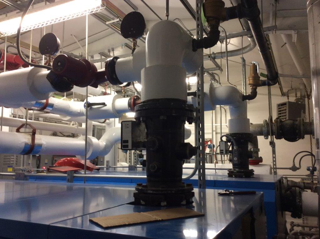
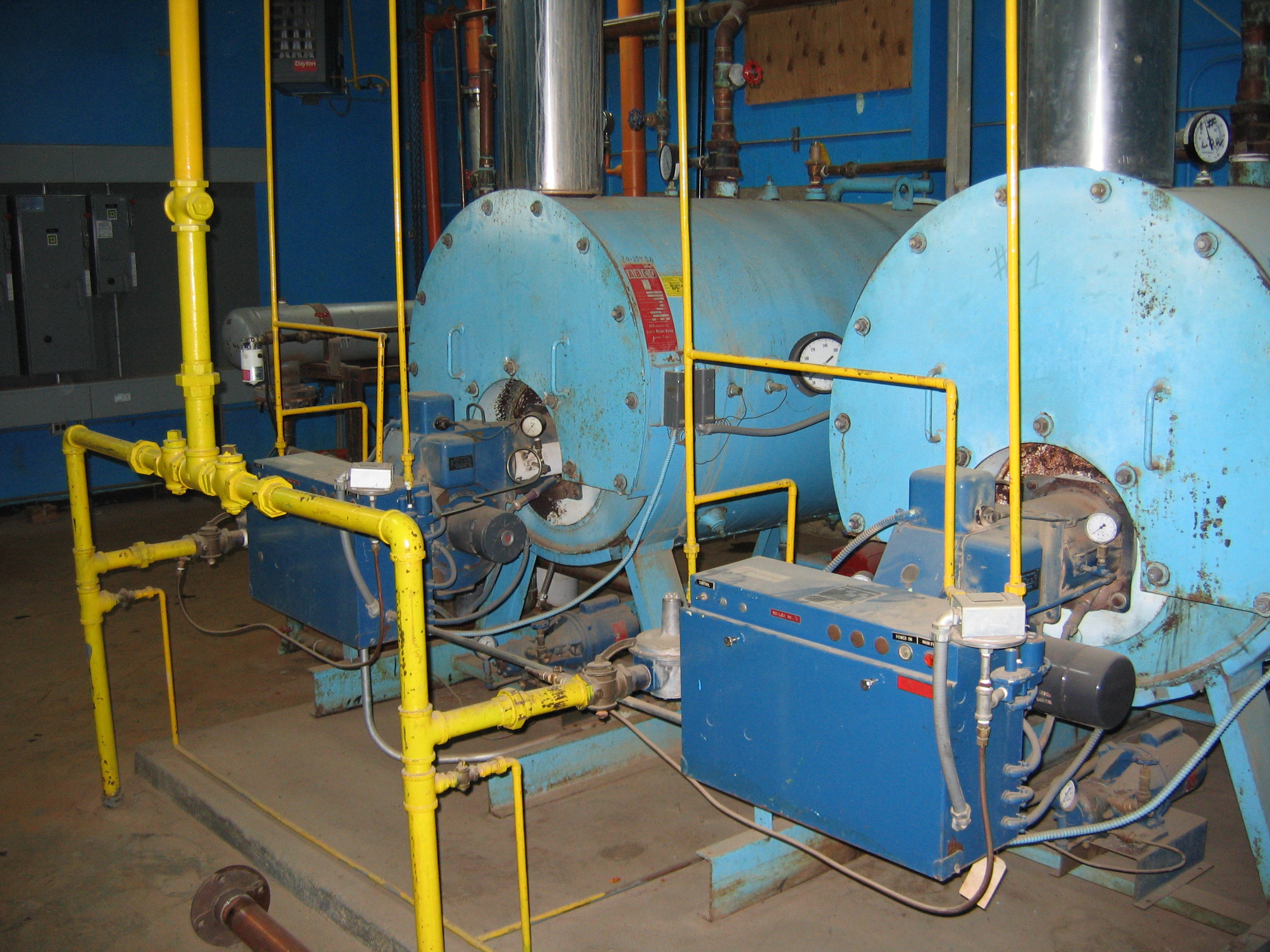
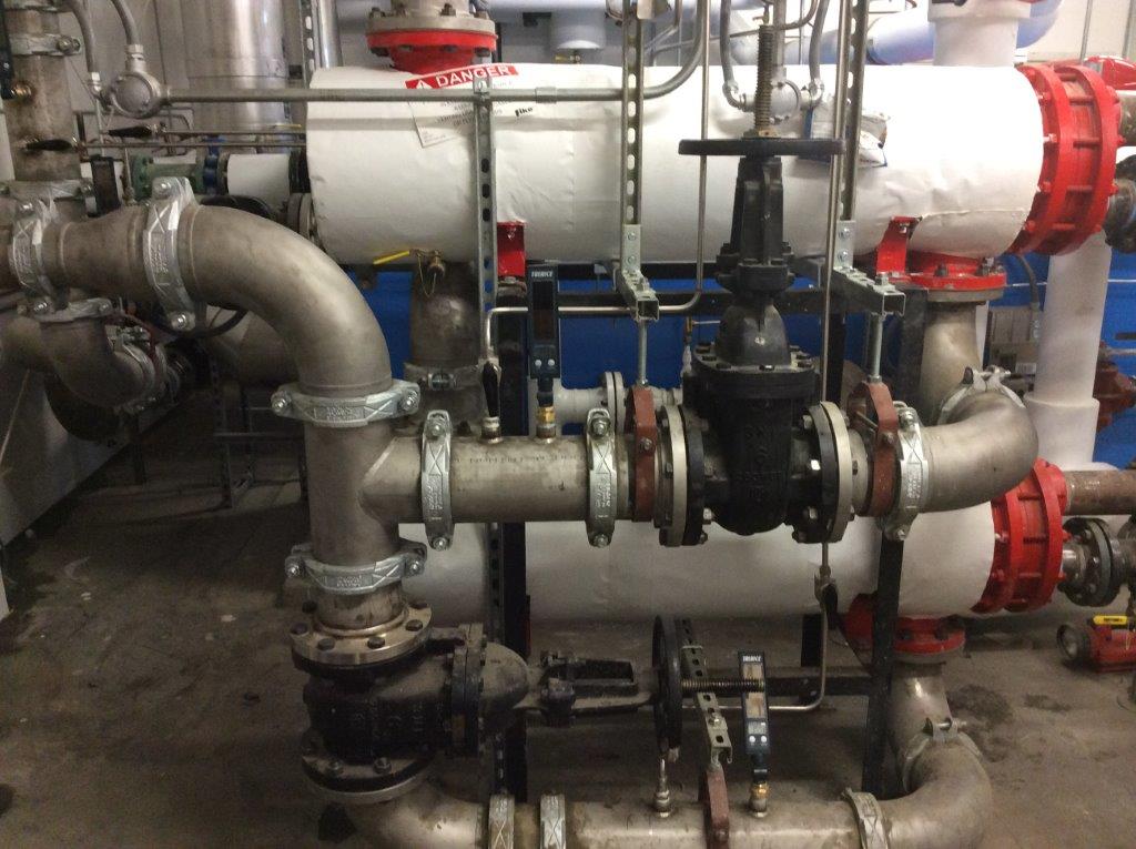 The new eqpuipment fit into the exisiting building, although piping criss-crosses the boilers. Large diameter piping was used in the new system in order to minimize the headloss, to help the pumps operate efficiently. As before, a total of four pumps were installed. One of the pumps is a much smaller, "jockey" pump, which is used to circualte water through the system when there is no demand. This keeps the pipes from freezing. The other three pumps are rated for the current demand of 325 gpm. When the dual membrane system is expanded, two pumps will be able to provide the water plant with 650 gpm, and the third pump will be on standby. The heat exchangers are designed to operate only one at a time until the water plant expansion, as are the boilers.
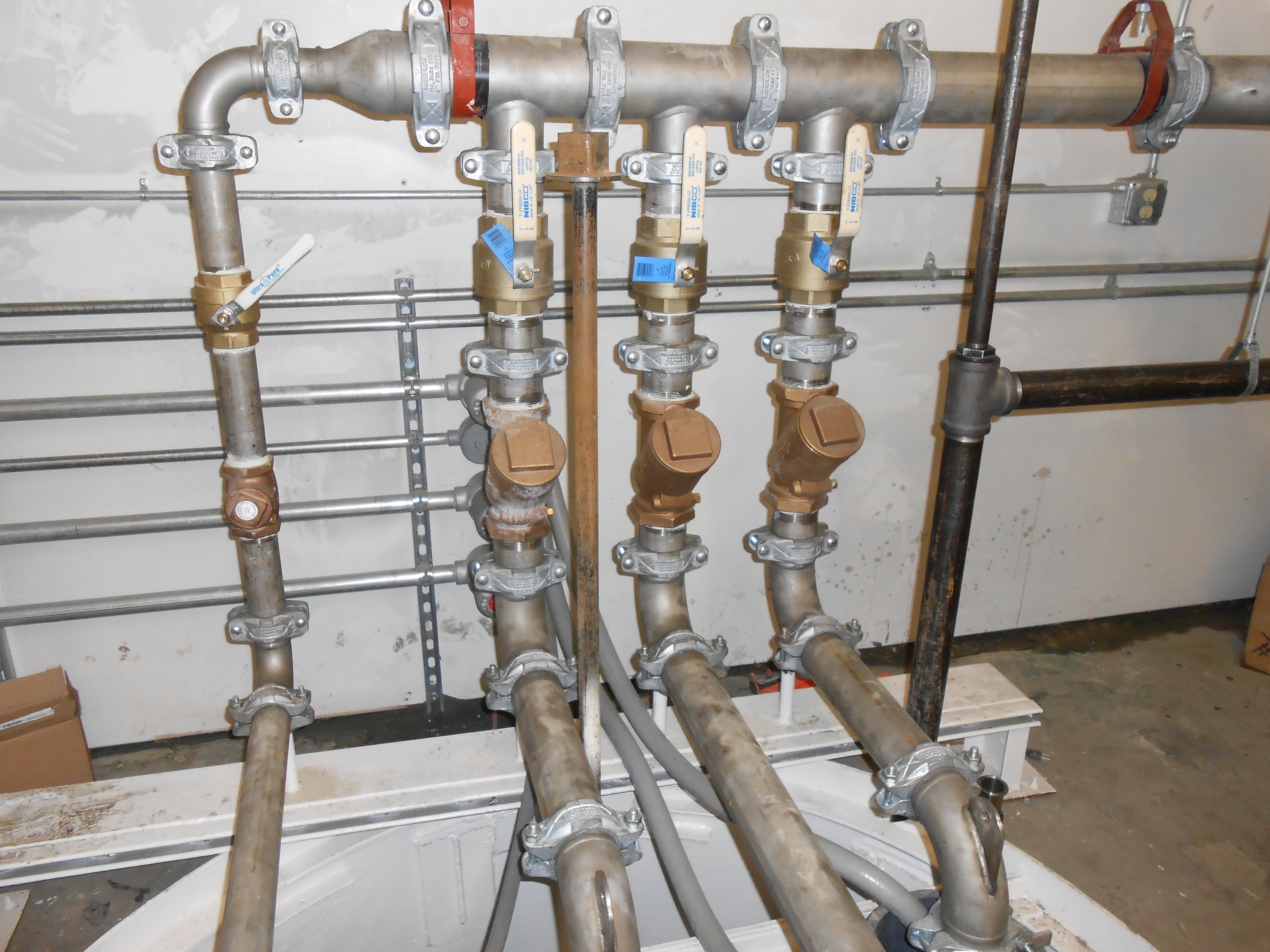
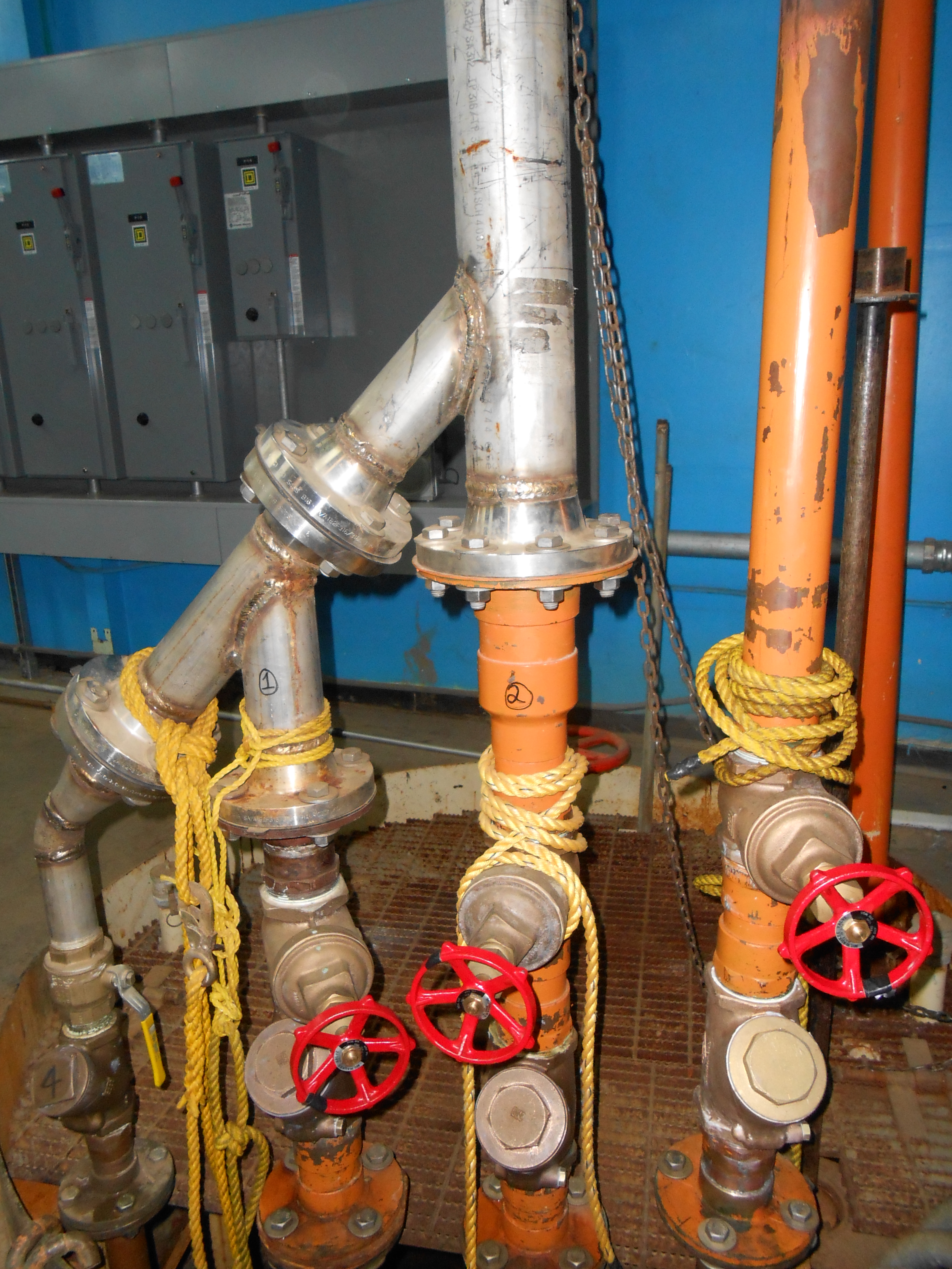
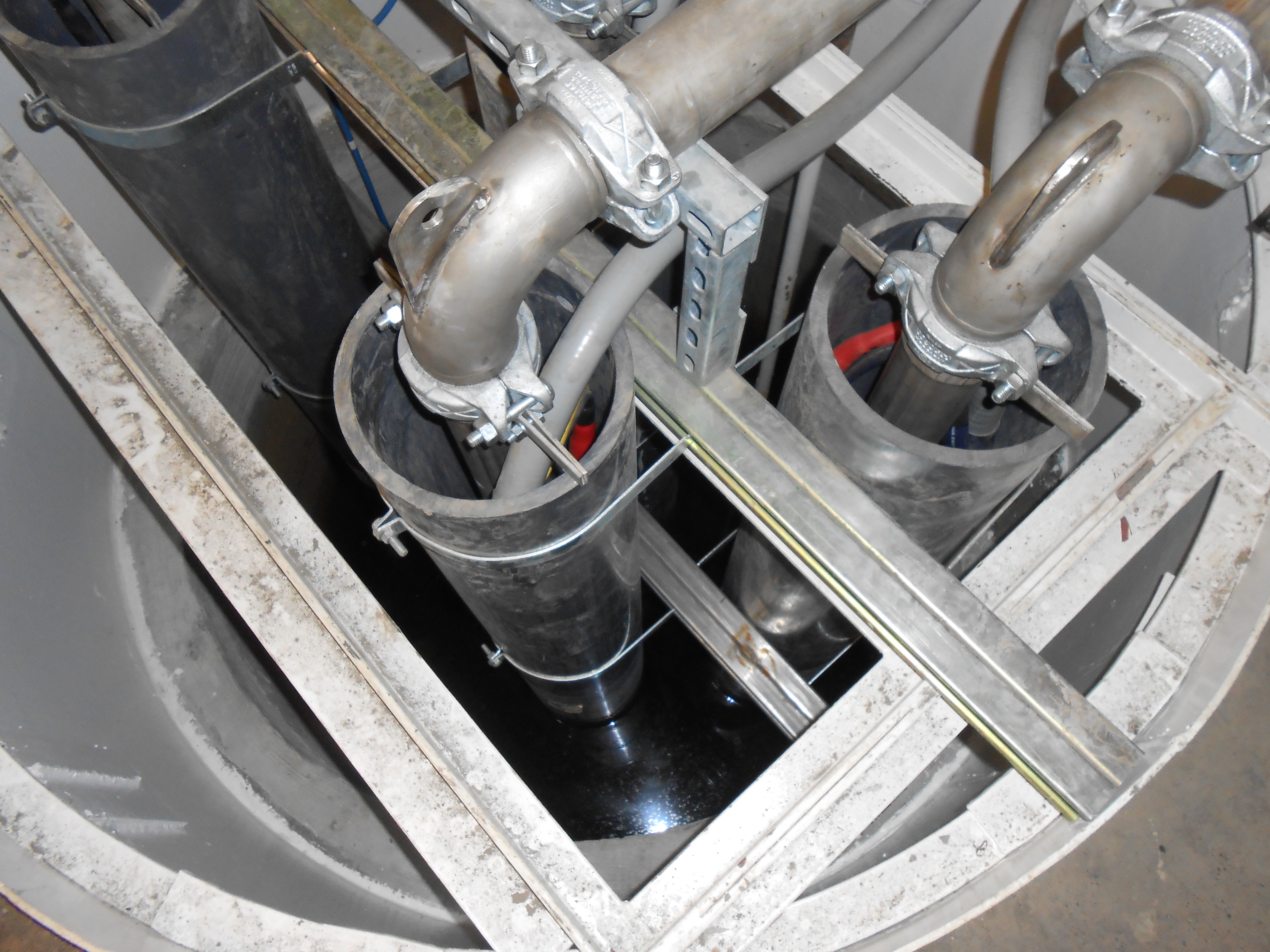 The manifold for the raw water pumps was considered very carefully during the design process and reconsidered during construction. Once work started in the wet well to rehabilitate the steel, the contractor determined the the steel casing was failing. The solution was to pour a three in thick ring of concrete, using the existing steel wet well as the outer diameter. This required that GVJ&A review the design of the manifold in order to make sure the pumps would still fit. There were existing valves and pipes to consider inside the wet well. Also, the submersible vertical turbine pumps needed to maintain a certain separation in order to avoid vortex formation and bubbles being pumped with the water. By rearranging, and rotating the original design by 90 degreees, the pumps were able to fit inot the slightly smaller wet well. The contracter constructed the wet well successfully and was able to install the pumps. The outlet piping was installed with a break halfway down in order to facilitate pulling th epump for maintenance.